

Utility Line Locator
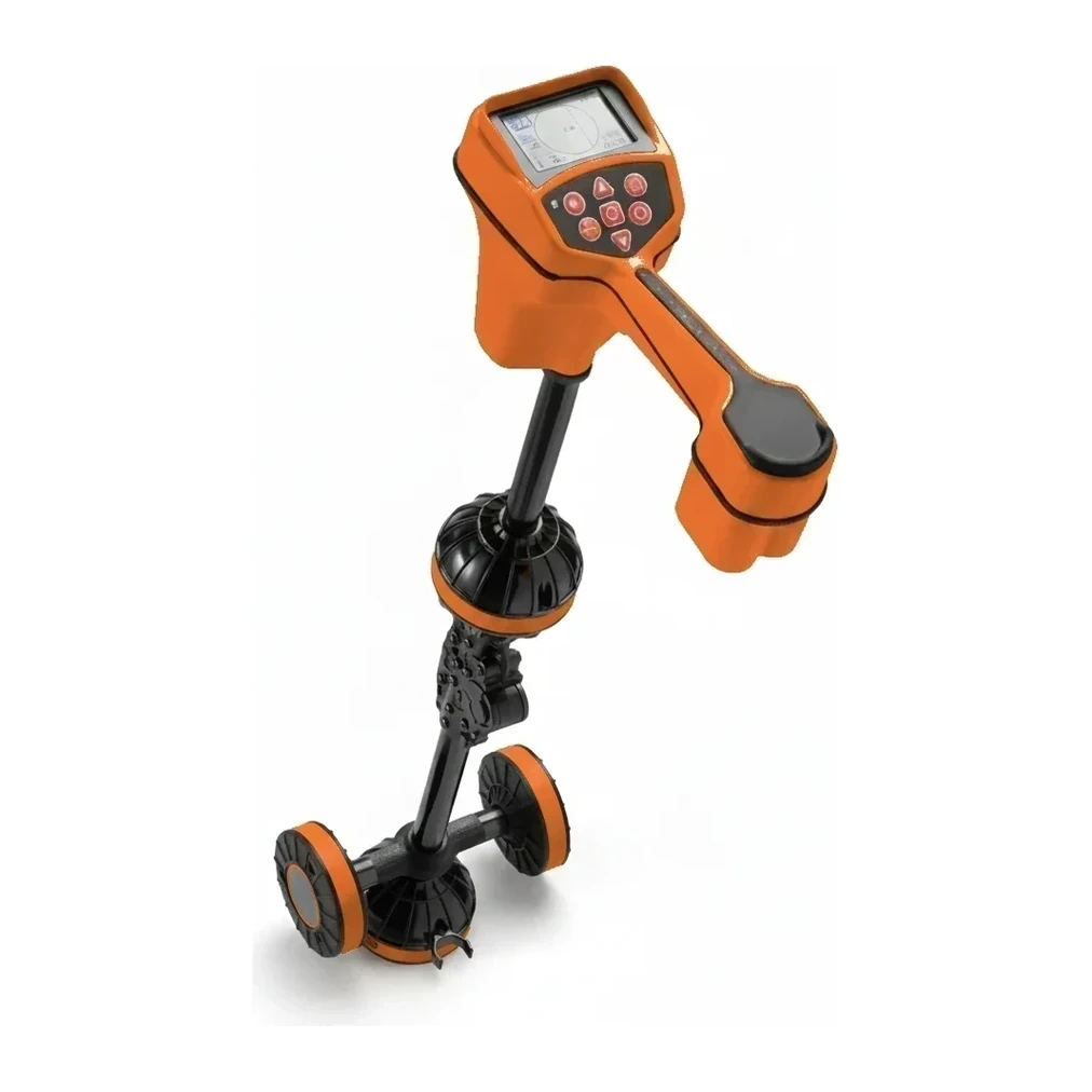
A utility line locator is an electromagnetic detection instrument used to identify and trace the position of underground utilities including water pipes, gas lines, electrical cables, telecommunications conduits, and sewer systems. The equipment typically consists of a transmitter that induces signals onto buried lines and a receiver that detects and interprets those signals to determine location and depth.
Cómo funciona
The transmitter applies an electromagnetic signal to the target utility either through direct connection, inductive coupling, or by detecting existing passive signals already present on energized lines. The signal travels along the conductive path of the utility, creating an electromagnetic field around it. The receiver detects this field using antenna coils and processes the signal strength, distortion, and phase to determine the horizontal position, depth, and sometimes current flow of the buried line. Operators move the receiver wand systematically across the search area, monitoring display readouts and audio tones that indicate signal strength and line position. Advanced models offer multiple frequency options (typically ranging from 512 Hz to 200 kHz) to accommodate different utility types, depths, and site conditions. GPS integration and data logging capabilities on modern units enable documentation of located utilities for mapping and compliance purposes.
Tipos y variantes
- Electromagnetic Pipe and Cable Locators
- Multi-frequency systems with separate transmitter and receiver units capable of tracing most metallic utilities; the most common type used for general underground utility detection
- Magnetic Locators
- Passive detection devices that identify ferrous metals through magnetic field distortion without requiring signal transmission; used primarily for valve covers, manhole lids, and iron pipes
- Sonde Locators
- Specialized receivers designed to track self-contained transmitting beacons (sondes) inserted into non-metallic pipes and conduits through push cameras or drain inspection equipment
- Ground Penetrating Radar (GPR) Systems
- Radar-based detection units that identify both metallic and non-metallic subsurface objects by analyzing reflected electromagnetic pulses; effective for concrete, plastic pipe, and complex congested sites
- All-in-One Locators
- Integrated single-unit devices combining transmitter and receiver functions in one housing; designed for compact portability on smaller-scale locating tasks
Especificaciones clave
| Especificación | Rango típico | Qué significa |
|---|---|---|
| Working Range | 150–610 ft (45.7–186 m) | Maximum effective detection distance from transmitter to receiver; determines coverage area and depth capability for locating operations |
| Operating Time | 6-50 hours | Battery runtime per charge or set; impacts field productivity and determines backup power requirements for extended locating projects |
| Reception Angle | 35-120° | Width of the electromagnetic field detection zone; wider angles provide easier initial signal acquisition while narrower angles offer greater precision |
| Weight | 0.1–0.9 lb (0.0–0.4 kg) | Mass of receiver unit (wand); affects operator fatigue during extended handheld use across large survey areas |
| Protection Rating | IP54-IP67 | Ingress protection level against dust and moisture; indicates suitability for wet conditions and harsh job site environments |
| Operating Temperature Range | -20°F to 50°C (122°F) | Environmental temperature limits for reliable operation; defines usability across seasonal conditions and geographic regions |
Cómo la industria lo dimensiona
Utility line locators are classified primarily by detection technology (electromagnetic, magnetic, GPR), frequency capabilities, and intended application rather than by physical dimensions. The industry segments models by feature sets including single-frequency versus multi-frequency operation, passive-only versus active tracing capability, depth measurement precision, and additional functions such as sonde compatibility, current measurement, or GPS integration. Professional-grade models supporting multiple frequencies (typically 512 Hz to 200 kHz) with advanced signal processing represent the standard for utility contractors and municipalities, while simpler single-frequency or passive-only units serve basic pipe and cable tracing needs. The 61 models available span brands including Vivax-Metrotech, Radiodetection, RIDGID, Subsite Electronics, and Schonstedt, with selection driven by utility types encountered, site complexity, and regulatory documentation requirements.
Aplicaciones
- Pre-excavation utility clearance and damage prevention prior to trenching, boring, or foundation work
- Municipal infrastructure mapping and asset management for water, sewer, gas, and electrical distribution systems
- Telecommunications and fiber optic cable tracing for network maintenance and expansion projects
- Plumbing diagnostics to locate underground service lines, cleanouts, and buried drain paths
- Electrical troubleshooting to trace conduit runs and identify faulted cable segments in underground distribution
- Construction site surveying to verify as-built utility positions and prevent conflicts with planned improvements
Seguridad y operación
- Always contact local one-call notification centers and obtain utility clearances before beginning excavation following locating operations
- Maintain awareness that locators indicate approximate position only; hand digging or vacuum excavation required for final utility exposure verification
- Use extreme caution when locating near high-voltage electrical lines; signals may jump between utilities causing false or misleading readings
- Verify equipment calibration and conduct test setups on known utilities before critical locating work to ensure proper system operation
- Account for signal distortion in areas with dense metallic congestion, reinforced concrete, or electromagnetic interference from power sources
Normas y certificaciones
- OSHA · 29 CFR 1926.651
- Excavation standard requiring identification and protection of underground utilities before trenching operations
- ANSI · Z535 Series
- Safety color code and signage standards applicable to utility marking and excavation zone identification
- Common Ground Alliance (CGA) · Best Practices
- Damage prevention guidelines establishing protocols for utility locating, marking, and excavation coordination
- APWA · Uniform Color Code
- American Public Works Association standard defining color-coding system for marking different utility types during locating operations
Preguntas frecuentes
What is the difference between active and passive locating modes?
Why are multiple frequency options important on utility locators?
Can utility locators detect non-metallic pipes and cables?
How accurate are depth readings provided by utility locators?
Equipos relacionados
Explorar por fabricante
Fuentes
Cada especificación se verifica con los datos publicados por el fabricante, con la fuente enlazada como referencia.
Todos los modelos
61 modelos · Página 2 de 2 · Cada especificación citada a la fuente