

Lifting and Spreader Beam
Lifting and spreader beams are structural rigging devices designed to distribute concentrated loads across multiple attachment points during crane lifts. These beams maintain load levelness, control sling angles, and prevent side loading on lifting eyes or equipment. They are essential in machinery moving, steel erection, and heavy module handling where load geometry or fragility demands precise rigging control.
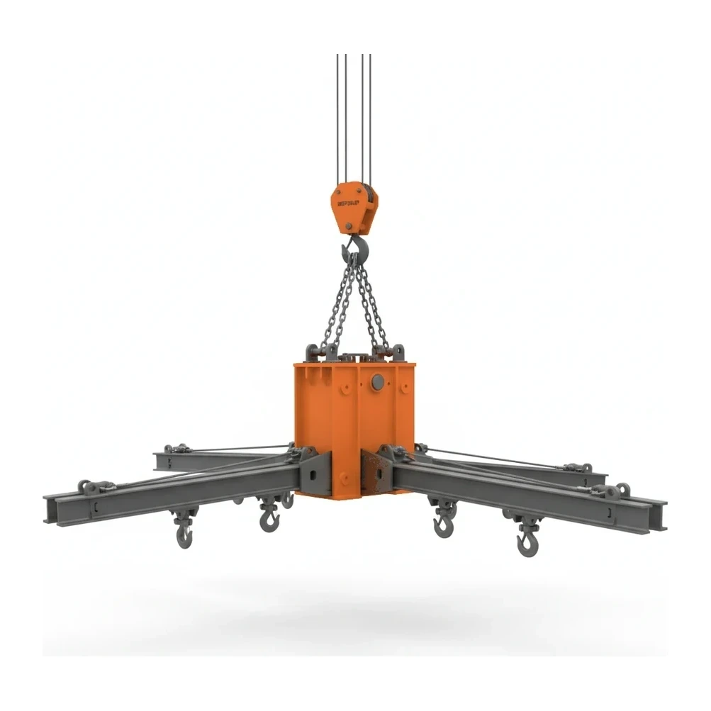
How it works
The beam spans above or below the load with a master lifting point at its center (or multiple points along its length) that connects to the crane hook. Secondary attachment points spaced along the beam distribute forces to the load via slings, shackles, or direct connections. The rigid structure maintains fixed geometry between attachment points, preventing sling angle collapse and keeping loads level during the pick. Load distribution depends on beam type: spreader beams use top rigging with the beam in compression, while lifting beams use bottom rigging with the beam in bending. The beam's structural capacity must account for the combined effects of load weight, sling angles, beam self-weight, and bending or compression forces. Proper rigging ensures the center of gravity aligns with the lifting point to prevent tilting.
Types & variants
- Fixed-Length Spreader Beam
- Non-adjustable beams with set attachment point spacing, typically custom-engineered for specific load configurations and maximum structural efficiency
- Adjustable Spreader Beam
- Telescoping or modular beams allowing variable attachment point spacing to accommodate different load widths and rigging geometries
- Lifting Beam (Below-the-Hook)
- Beams rigged below the load with bottom attachment points, subjecting the beam to bending forces rather than compression
- Multi-Point Spreader Beam
- Beams with more than two load attachment points, distributing forces across three or more rigging locations for long or complex loads
- Modular Beam System
- Configurable beam assemblies using interchangeable sections and hardware to create custom lengths and capacities for varied applications
Key specifications
| Specification | Typical range | What it means |
|---|---|---|
| Capacity (tons) | Commonly available from 2 to 50+ tons | Maximum safe working load the beam can support under specified rigging configurations and sling angles |
| Beam Length | Ranges from 4 to 40+ feet depending on application | Overall span of the beam determining attachment point spacing and load distribution geometry |
| Attachment Point Configuration | 2-point, 4-point, or custom multi-point | Number and spacing of rigging points along the beam for connecting to the load |
| Beam Weight | Varies from 100 lbs to several tons | Self-weight of the beam that must be deducted from crane capacity and considered in rigging calculations |
| Design Factor | Typically 3:1 or 5:1 per ASME standards | Ratio of ultimate strength to working load limit, providing structural safety margin |
How the industry sizes it
The industry sizes lifting and spreader beams primarily by capacity in tons, which reflects the maximum safe working load under specified rigging conditions. Beams under 5 tons handle lighter loads requiring levelness and sling angle control on short picks. The 5-15 ton range represents standard beams for steel components, tanks, and long loads that must remain level during placement. Beams rated above 15 tons serve heavy engineered lifts including vessels, modules, and long precast concrete elements. Sizing also considers beam length and attachment point configuration, as these geometric factors directly affect load distribution, bending moments, and permissible sling angles for the rated capacity.
Applications
- Steel erection and structural component installation requiring level picks and controlled load orientation
- Tank and vessel lifting where concentrated lifting eyes must be protected from excessive side loads
- Precast concrete panel and beam placement demanding precise levelness during setting operations
- Machinery relocation and heavy equipment moves requiring multi-point load distribution
- Long or awkward loads where sling geometry alone would create unsafe angles or load instability
- Module and skid lifts in industrial construction where rigging points are widely spaced
Safety & operation
- Verify beam capacity accounts for actual load weight, sling angles, and beam self-weight before rigging
- Inspect beam structure, welds, and attachment points for cracks, deformation, or damage prior to each use
- Ensure load center of gravity aligns with the master lifting point to prevent beam rotation or tipping
- Confirm sling angles remain within beam design parameters, as excessive angles reduce capacity and increase beam stress
- Use only qualified riggers to design lifting configurations and supervise critical picks involving spreader beams
Standards & certifications
- ASME · B30.20
- Safety standard for below-the-hook lifting devices including spreader and lifting beams, covering design factors and operational requirements
- ASME · BTH-1
- Design standard for below-the-hook lifting devices specifying structural analysis, material requirements, and safety factors
- OSHA · 1926.753
- Steel erection standard addressing rigging requirements and safe practices for structural lifts commonly using spreader beams
- ANSI · Z359
- Fall protection standards applicable when personnel work at height during beam rigging and load attachment operations
Frequently asked
What is the difference between a spreader beam and a lifting beam?
How does sling angle affect spreader beam capacity?
When is a spreader beam required instead of direct sling rigging?
How is spreader beam capacity calculated for a specific lift?
Related equipment
Browse by manufacturer
Sources
Every specification is verified against the manufacturer's published data, with the source linked for reference.
All models
1 models · Every spec cited to source