

Beam Trolley
A beam trolley is a wheeled carriage designed to ride along the bottom flange of an I-beam or structural rail, enabling horizontal movement of hoists and suspended loads. These devices connect chain hoists or other lifting equipment to overhead runway beams, allowing loads to be positioned precisely within a work area. Beam trolleys are foundational components in material handling systems across industrial facilities, fabrication shops, and maintenance operations.
Cat classes
Choisissez une classe de taille : la capacité et la portée varient selon la gamme.
Fonctionnement
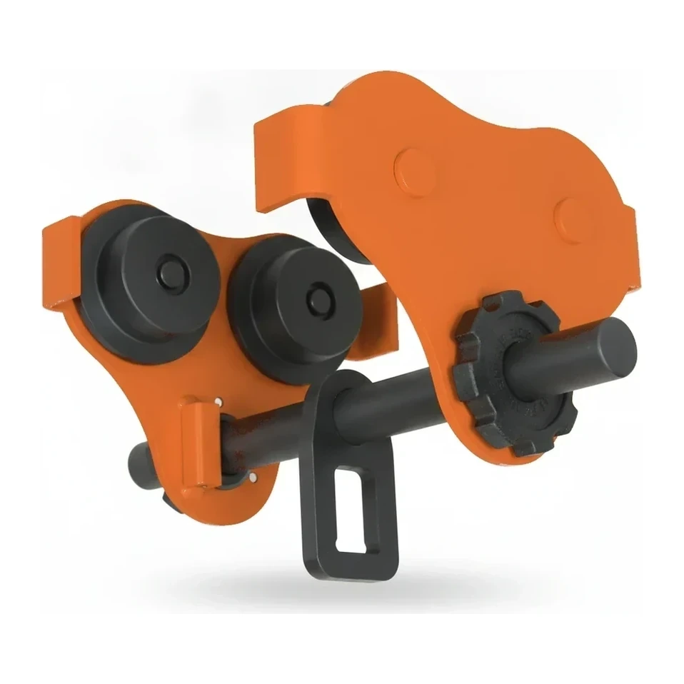
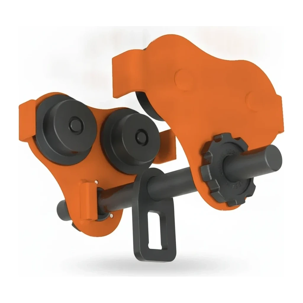
The trolley consists of a frame housing multiple wheels or rollers that ride on the lower flange of an I-beam. In push trolleys, operators manually move the trolley by hand or with a load hook; in geared trolleys, an endless hand chain drives a gear mechanism to traverse the beam with mechanical advantage. The trolley frame includes a mounting point or integrated connection for suspending a hoist or lifting device below. Load-bearing wheels distribute weight across the beam flange, while side roller guides prevent lateral movement and keep the trolley aligned during travel. The trolley must match the specific beam flange width and profile it will ride upon. Geared models incorporate reduction gearing that allows controlled movement of heavy loads with minimal operator effort, while plain push models rely on low-friction wheels for manual positioning.
Types et variantes
- Push Trolley
- Manual trolley moved by hand or by pulling the suspended load; simple wheel-based design for light to moderate capacities where precise positioning is less critical.
- Geared Trolley
- Hand-chain operated trolley with internal gearing providing mechanical advantage; allows controlled movement of heavy loads and precise positioning with reduced operator effort.
- Low-Headroom Trolley
- Compact design minimizing vertical clearance between beam and hoist hook; used in facilities with limited overhead space or where maximum hook height is required.
- Plain Trolley (Fixed Suspension)
- Basic four-wheel or multi-wheel carriage without integrated hoist connection; serves as mounting platform for separate chain hoists or lifting devices.
- Articulating Trolley
- Trolley with pivoting connection point allowing the suspended load to swing or rotate; accommodates angled pulls and reduces side loading on the beam.
Spécifications clés
| Spécification | Plage typique | Signification |
|---|---|---|
| Load Capacity | 500-20,000 kg (0.5-20 t) | Maximum weight the trolley can safely support while traversing the beam, including hoist and load. |
| Beam Flange Width | 58-229 mm (varies by beam profile) | Range of I-beam lower flange widths the trolley wheels are designed to ride upon; must match the structural beam. |
| Wheel Configuration | 4, 8, or 16 wheels | Number of load-bearing wheels distributing weight across the beam flange; more wheels reduce point loading and rolling resistance. |
| Gear Ratio | 3:1 to 8:1 (geared models) | Mechanical advantage provided by internal gearing; higher ratios reduce hand chain pull force for heavier loads. |
| Tread Type | Steel, bronze, or nylon wheels | Wheel material affecting durability, rolling friction, and suitability for indoor or outdoor beam surfaces. |
Comment l'industrie le dimensionne
The industry sizes beam trolleys by their rated lifting capacity in tons, typically ranging from 0.5 to 20 tons. Capacity selection must account for the combined weight of the hoist and the maximum suspended load. Trolleys are further specified by the beam flange width they accommodate, as wheel spacing must match the specific I-beam profile (e.g., W8, W10, S-beam). Light-duty trolleys under 2 tons suit positioning tasks with small hoists; standard 2-5 ton models pair with common shop chain hoists; heavy-duty trolleys above 5 tons support industrial runway systems handling 10 tons and up.
Applications
- Supporting chain hoists on overhead I-beam runways in fabrication and assembly shops
- Positioning suspended loads along monorail systems in manufacturing facilities
- Moving heavy components during maintenance operations in power plants and refineries
- Traversing loads across bridge crane runways and gantry systems
- Material handling in steel service centers and metal processing operations
- Loading and unloading operations in warehouses with overhead beam infrastructure
Sécurité et opération
- Verify trolley load capacity exceeds the combined weight of hoist and maximum lifted load, with appropriate safety factor
- Inspect beam flanges for damage, corrosion, or obstructions that could derail or bind the trolley during travel
- Ensure trolley wheel spacing and profile match the I-beam dimensions; mismatched components risk derailment or structural failure
- Check that support beam is rated for the imposed load and that beam span meets structural engineering requirements
- Maintain clear zones below trolley paths and use taglines or guide ropes to control load swing during horizontal travel
Normes et certifications
- ASME · B30.16
- Safety standard for overhead hoists (underhung), covering trolley design, inspection, and operation requirements.
- ASME · B30.11
- Addresses monorails and underhung cranes, including trolley components and runway beam specifications.
- OSHA · 1910.179
- Overhead and gantry crane regulations applicable to trolley-equipped runway systems in general industry.
- ANSI · MH16.1
- Design specification for overhead traveling cranes, hoists, and trolley equipment used in material handling.
Questions fréquentes
What is the difference between a push trolley and a geared trolley?
How is trolley capacity different from hoist capacity?
Can a trolley be used on any I-beam?
What determines whether a plain or low-headroom trolley is needed?
Comparer les modèles populaires
Chercher par spécification →Normalisé aux mêmes unités. Un tiret signifie que la valeur n'a pas été publiée.
| Modèle | Capacité de charge | Hauteur de levage | Puissance moteur |
|---|---|---|---|
| Harrington UBC Universal Beam Clamp | 2,205 lb (1,000 kg) | - | - |
| Jekko JIB1000GR | 2,205 lb (1,000 kg) | - | - |
| Jekko JLB05 | 11,023 lb (5,000 kg) | - | - |
| Jekko JLB10 | 22,046 lb (10,000 kg) | - | - |
| Jekko JLB20 | 44,092 lb (20,000 kg) | - | - |
Équipements connexes
Parcourir par fabricant
Sources
Chaque spécification est vérifiée par rapport aux données publiées par le fabricant, avec la source liée pour référence.